Introduction of TRANSFORMER, Basic Construction and principle of Working & E.M.F. Equation.
A transformer is an ac machine that
- Transfers electrical energy from one electrical circuit to another
- Does so without a change of frequency
- Does so by the principle of electromagnetic induction
- Transformer has an electric circuit that is linked by a common magnetic circuit
The energy transfer usually takes place with a change in voltage, although this is not always necessary. Since its basic construction requires no moving part, so it is often called 'static device and it is very rugged machine requiring the minimum amount of repair and maintenance.
When the transformer raises the voltage, i.e. when the output voltage of a transformer is higher than its input voltage, it is called a step-up transformer and
when the output voltage is lowered, it is called step-down transformer.
Transformer - The Basic Construction and Principle of Working:
An elementary transformer consists of a soft iron or silicon steel core and the two windings, place on it. The windings are insulated from both the core by each other. The core is built up of thin soft iron or silicon steel laminations to provide a path of low reluctance to the magnetic flux.
The winding connected to the supply main is called the 'Primary' and the winding connected to the load circuit is called the 'secondary'.
Although in the actual construction the two windings are usually wound one over the other but for the sake of clearity, the figures for analysing transformer theory show the windings on opposite sides of the core.
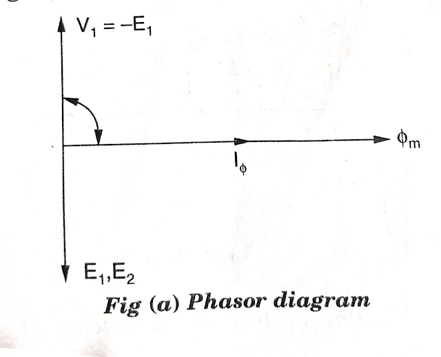
When the primary is connected to an alternating source, an alternating current I𝞍, starts to flow through N1 w inding. This current produces flux 𝞍 which inudces an e.m.f in the primary winding E1 in opposition to applied voltage. This flux 𝞍 also links with the secondary winding and induces E2 e.m.f in this circuit.
E.M.F Equation:
From this equation,
e.m.f. per turn in primary = e.m.f. per turn in secondary
IDEAL TWO WINDING TRANSFORMER:
When it is assumed an ideal, then various assumptions are:
1. Winding resistance are negligible.
2. All the flux is confined to the magnetic core.
3. The core losses are negligible.
4. The core has constant permeabiliity, i.e. the magnetiztion curve for the is linear.
When switch S is closed, I.e. load gets connected. This connection will draw secondary current I2, which sets up N2I2, the secondary m.m.f. and it opposes the main flux 𝞍 m.
The secondary m.m.f. F2 weakens the main flux 𝞍 m. But any reduction in 𝞍 m reduces E1 and in case of ideal transformer v1 = - E1. Hence an extra load component of current I'1 from primary will draw to compensate.


.png)


